high-pass filter — перевод на русский
Applications
Audio
High-pass filters have many applications. They are used as part of an to direct high frequencies to a while attenuating bass signals which could interfere with, or damage, the speaker. When such a filter is built into a cabinet it is normally a that also includes a for the and so often employs both a capacitor and (although very simple high-pass filters for tweeters can consist of a series capacitor and nothing else).
As an example, the , applied to a tweeter with R=10 Ohm, will determine the capacitor value for a cut-off frequency of 5 kHz.
C=12πfR=16.28×5000×10=3.18×10⁻⁶{\displaystyle C={\frac {1}{2\pi fR}}={\frac {1}{6.28\times 5000\times 10}}=3.18\times 10^{-6}}, or approx 3.2 μF.
An alternative, which provides good quality sound without inductors (which are prone to parasitic coupling, are expensive, and may have significant internal resistance) is to employ with or active digital filters with separate power amplifiers for each . Such low-current and low-voltage crossovers are called .
Rumble filters are high-pass filters applied to the removal of unwanted sounds near to the lower end of the or below. For example, noises (e.g., footsteps, or motor noises from and ) may be removed because they are undesired or may overload the circuit of the .
High-pass filters are also used for at the inputs of many , for preventing the amplification of DC currents which may harm the amplifier, rob the amplifier of headroom, and generate waste heat at the . One amplifier, the model DC300 made by beginning in the 1960s, did not have high-pass filtering at all, and could be used to amplify the DC signal of a common 9-volt battery at the input to supply 18 volts DC in an emergency for power. However, that model’s basic design has been superseded by newer designs such as the Crown Macro-Tech series developed in the late 1980s which included 10 Hz high-pass filtering on the inputs and switchable 35 Hz high-pass filtering on the outputs. Another example is the PLX amplifier series which includes an internal 5 Hz high-pass filter which is applied to the inputs whenever the optional 50 and 30 Hz high-pass filters are turned off.
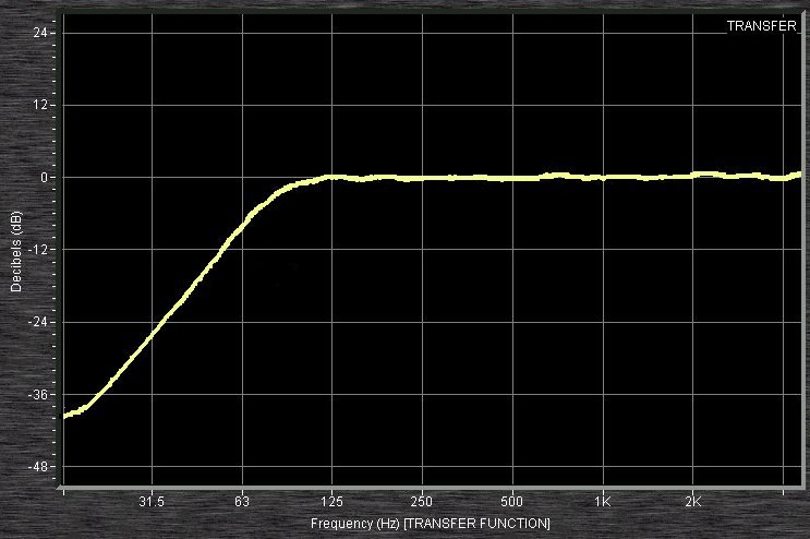
A 75 Hz «low cut» filter from an input channel of a 1402 as measured by software. This high-pass filter has a slope of 18 dB per octave.
Mixing consoles often include high-pass filtering at each . Some models have fixed-slope, fixed-frequency high-pass filters at 80 or 100 Hz that can be engaged; other models have sweepable high-pass filters, filters of fixed slope that can be set within a specified frequency range, such as from 20 to 400 Hz on the Heritage 3000, or 20 to 20,000 Hz on the . Veteran systems engineer and live sound mixer Bruce Main recommends that high-pass filters be engaged for most mixer input sources, except for those such as , and piano, sources which will have useful low frequency sounds. Main writes that inputs (as opposed to inputs) do not need high-pass filtering as they are not subject to modulation by low-frequency —low frequency sounds coming from the or the system and wrapping around to the stage. Main indicates that high-pass filters are commonly used for directional microphones which have a —a low-frequency boost for very close sources. This low frequency boost commonly causes problems up to 200 or 300 Hz, but Main notes that he has seen microphones that benefit from a 500 Hz high-pass filter setting on the console.
Image

Example of high-pass filter applied to the right half of a photograph. Left side is unmodified, Right side is with a high-pass filter applied (in this case, with a radius of 4.9)
High-pass and low-pass filters are also used in digital to perform image modifications, enhancements, noise reduction, etc., using designs done in either the or the . The , or sharpening, operation used in image editing software is a high-boost filter, a generalization of high-pass.
First-order continuous-time implementation
Figure 1: A passive, analog, first-order high-pass filter, realized by an
The simple first-order electronic high-pass filter shown in Figure 1 is implemented by placing an input voltage across the series combination of a and a and using the voltage across the resistor as an output. The product of the resistance and capacitance (R×C) is the (τ); it is inversely proportional to the cutoff frequency fc, that is,
- fc=12πτ=12πRC,{\displaystyle f_{c}={\frac {1}{2\pi \tau }}={\frac {1}{2\pi RC}},\,}
where fc is in , τ is in , R is in , and C is in .
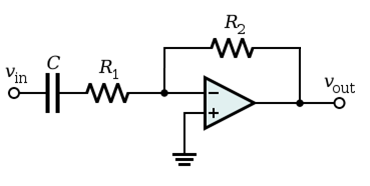
Figure 2: An active high-pass filter
Figure 2 shows an active electronic implementation of a first-order high-pass filter using an . In this case, the filter has a gain of —R2/R1 and has a cutoff frequency of
- fc=12πτ=12πR1C,{\displaystyle f_{c}={\frac {1}{2\pi \tau }}={\frac {1}{2\pi R_{1}C}},\,}
Because this filter is , it may have passband gain. That is, high-frequency signals are inverted and amplified by R2/R1.